|
Rigid-Flex PCBs: Complete Guide to Design, Manufacturing, Benefits & Applications
|
|
|
|
July 03, 2026 | Mega Plus PCB
Electronic products continue to shrink in size while performance expectations increase. Traditional rigid PCBs provide structural stability and straightforward component mounting, while flexible circuits that conform to the device shape in wearables allow bending and folding. Each technology serves a purpose; however, many modern products require both. Rigid-flex PCBs address this requirement by combining rigid and flexible sections into a single integrated structure. For OEMs and contract manufacturers developing aerospace, medical, automotive, telecommunications, and industrial products, rigid-flex technology offers a practical solution to common design and assembly challenges. This post discusses rigid-flex PCBs at length including their benefits, types, applications, and more.
|
|
|
|
What is Rigid-Flex PCB?
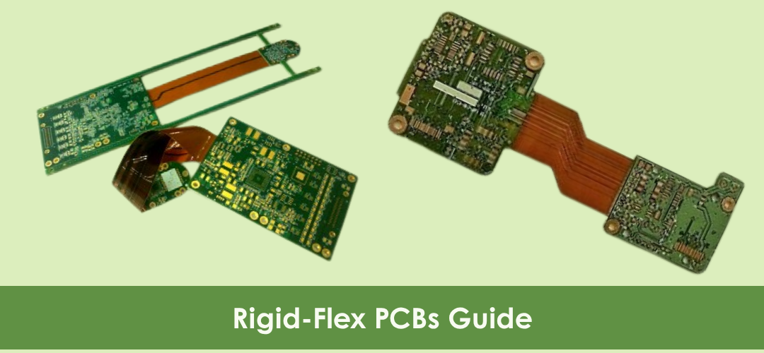
A rigid-flex PCB is a hybrid circuit board that integrates rigid PCB sections and flexible circuit layers into one interconnected assembly. The rigid portions provide mechanical support and serve as component mounting areas. The flexible sections allow the board to bend, fold, or fit into confined spaces. Unlike conventional assemblies that rely on connectors and wiring harnesses, rigid-flex boards incorporate these interconnections directly into the PCB structure. Their key characteristics include:
- Combination of rigid FR4 and flexible polyimide materials.
- Continuous copper conductors across rigid and flex regions.
- Support for compact three-dimensional assemblies.
- Availability in multilayer configurations.
|
|
|
|
|
Advantages of Rigid-Flex PCBs
Rigid-flex technology offers several advantages over traditional multi-board assemblies. Their integrated construction reduces interconnect failures while improving mechanical and electrical performance.
- Space and Weight Reduction: Eliminating connectors, cables, and secondary assemblies allows engineers to reduce both product size and weight. This is particularly valuable in aerospace systems, portable medical devices, wearables, and compact consumer electronics.
- Improved Reliability: Connectors and solder joints are common failure points in electronic assemblies. By reducing these interconnections, rigid-flex boards improve long-term reliability and reduce maintenance requirements.
- Enhanced Signal Integrity: Shorter signal paths and fewer interconnect transitions help reduce signal loss and electromagnetic interference. This supports better performance in high-speed digital, RF, and mixed-signal applications.
- Improved Mechanical Performance: Flexible sections absorb vibration and mechanical stress more effectively than traditional board-to-board connections. As a result, rigid-flex PCBs are frequently used in demanding environments such as aircraft, industrial equipment, and automotive systems.
- Simplified Assembly: Rigid-flex PCBs can consolidate multiple rigid boards and internal board-to-board wiring into a single integrated assembly. This reduces assembly steps, lowers labor requirements, and improves manufacturing consistency.
|
|
|
|
|
Types of Common Rigid-Flex PCB Configurations
Rigid-flex PCBs can be designed in different configurations depending on mechanical movement, routing density, and electrical complexity. Here are some of the most common rigid-flex PCB configurations used across industries:
- Static Rigid-Flex: Static designs are bent during installation and remain fixed afterward. They are commonly used in consumer electronics, medical devices, and industrial controls..
- Dynamic Rigid-Flex: Dynamic designs are engineered to withstand repeated bending and movement throughout their service life. Applications include robotics, printers, and hinged display assemblies.
- HDI Rigid-Flex: High-Density Interconnect (HDI) rigid-flex boards combine fine-line traces, microvias, and dense component placement with flexible construction. These designs support compact products with high routing density.
- Multilayer Rigid-Flex: Products with complex signal routing requirements often use multilayer constructions with four or more layers. These configurations are widely used in aerospace, telecommunications, and industrial systems.
|
|
|
|
|
Materials Used in Rigid-Flex PCB Manufacturing
Flexible PCBs are not suitable for every application, but they excel in specific use cases where rigid boards are limited. One needs to weigh flex PCB pros and cons against your application requirements.
The performance, durability, and long-term reliability of a rigid-flex PCB depend heavily on the materials used in its construction. Here are some of the most commonly used materials in rigid-flex PCB manufacturing:
- Polyimide is the standard material used in flexible sections due to its excellent thermal stability and flexibility..
- FR4 is commonly used in rigid areas because of its mechanical strength and electrical insulation properties.
- Copper foil forms the conductive pathways. For dynamic flex applications, rolled annealed copper is generally preferred as it offers better resistance to fatigue from repeated bending.
- Coverlays provide insulation and environmental protection for flexible circuits, while adhesiveless laminates improve dimensional stability and extend flex life in demanding applications.
|
|
|
|
|
|
Rigid-Flex PCB Manufacturing Process
Rigid-flex PCB manufacturing requires specialized fabrication techniques and process control. Here are the key stages involved in rigid-flex PCB manufacturing:
- Design Review: The process begins with a design review to verify bend areas, layer stack-up, impedance requirements, and manufacturability. This step helps identify potential reliability risks before fabrication begins.
- Material Selection: Materials are selected separately for rigid and flex portions based on the intended application, including operating temperature, flex cycle requirements, environmental exposure, and any applicable regulatory standards.
- Circuit Pattern Formation: Circuit patterns are formed using photolithography and etching processes. Rigid and flexible layers are subsequently laminated under controlled temperature and pressure conditions to create a unified structure.
- Drilling and Via Formation: Precision drilling creates through holes, blind vias, and buried vias where required. Electroplating establishes electrical connections between layers.
- Coverlay and Surface Protection: Coverlays are applied to flexible sections for insulation and protection, while solder masks are typically applied to rigid sections. These layers help protect the circuitry from environmental exposure and mechanical stress.
- Surface Finishing: Surface finishes such as ENIG, immersion silver, immersion tin, or OSP are then applied to prepare exposed pads for component assembly and soldering.
- Testing and Inspection: Before shipment, boards undergo electrical testing, visual inspection, dimensional verification, and other quality checks to ensure compliance with design requirements.
|
|
|
|
|
|
Common Failure Modes
Rigid-flex boards are complex because of the combinations of materials with varying structures, consistencies, and more. Understanding what can go wrong in a rigid-flex PCB helps engineers design around those failure modes from the start. Here are some of the most common failure modes seen in rigid-flex PCB designs and how they can be prevented:
Particular attention should be paid to bend radius requirements and copper selection in dynamic flex applications as these are among the most common sources of premature failure.
Quality Standards and Certifications
Rigid-flex PCBs are often designed and manufactured in accordance with established industry standards to support reliability, performance, and regulatory compliance. Following these standards helps improve design consistency, manufacturing quality, and product acceptance across different industries. Here are some of the key standards and certifications commonly associated with rigid-flex PCB manufacturing:
- IPC-2223: This standard provides design guidelines specifically for flexible and rigid-flex circuits, covering important factors such as bend radius requirements, conductor spacing, material selection, and flex-region design considerations.
- IPC Product Classifications: Class 1 applies to general consumer electronics, Class 2 covers dedicated-service electronic products, and Class 3 is intended for high-reliability, mission-critical applications such as aerospace, defense, and medical systems.
Industry Certifications: Depending on the application and target market, rigid-flex PCB manufacturing may also require certifications such as ISO 9001 for quality management, UL for product safety, RoHS for environmental compliance, AS9100 for aerospace systems, and ISO 13485 for medical device manufacturing.
Rigid-Flex PCB Applications
Rigid-flex PCBs are widely used across the following industries where space constraints and reliability are critical:
- Aerospace and Defense: Rigid-flex boards find use in avionics, radar systems, satellite electronics, and military communications.
- Medical: Rigid-flex PCBs support applications such as diagnostic equipment, implantable devices, patient monitoring systems, and surgical instruments.
- Automotive Electronics: Rigid-flex boards are commonly integrated into ADAS systems, EV battery management systems, infotainment platforms, and sensor networks.
- Consumer Electronics: Rigid-flex PCBs find use in smartphones, cameras, tablets, wearables, and foldable devices.
- Industrial Automation: Rigid-flex PCBs are used in robotics, PLC systems, industrial sensors, and factory automation equipment.
- Telecommunications: Rigid-flex boards play an important role in RF systems, network infrastructure, base stations, and high-speed communication hardware.
|
|
|
|
|
|
Rigid-flex PCBs solve crucial engineering problems that neither rigid boards nor flexible circuits can solve independently. They offer practical solutions to OEMs and contract manufacturers operating in aerospace, medical, automotive, and telecommunications. However, it is important to partner with an experienced rigid-flex PCB manufacturer to ensure that your designs receive proper engineering support, quality manufacturing, and reliable delivery from initial prototype through full production volume. At Mega Plus PCB, we support clients with our engineering expertise and advanced manufacturing capabilities to help bring rigid-flex PCB designs from prototype through volume production.
Request a Quote
|
|
|
|
|
FAQs
What is the recommended bend radius for a rigid-flex PCB?
Bend radius depends on material thickness, copper type, and whether the application is static or dynamic. As a general principle, dynamic applications require larger bend radii than static ones, and thicker copper requires a larger radius than thinner copper.
Are rigid-flex PCBs more expensive than traditional PCBs?
Per-board manufacturing costs are higher due to specialized materials and fabrication processes. However, total system cost often decreases. Eliminating connectors, cables, and assembly labor can help offset the higher board cost in many applications.
How long do rigid-flex PCBs last?
Properly designed rigid-flex boards can last for many years in service. Lifespan depends on operating conditions, environmental exposure, and adherence to design guidelines during the development phase.
Can rigid-flex PCBs support high-speed and RF applications?
Yes. Rigid-flex PCBs can be engineered with controlled impedance structures, HDI technology, and optimized signal routing for high-speed digital, RF, and mixed-signal applications.
|
|
|
|