|
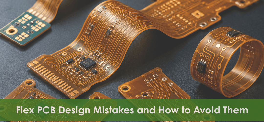
Top 10 Common Flex PCB Design Mistakes and How to Avoid Them
|
|
|
|
April 15, 2025 | Mega Plus PCB
As electronic devices become smaller and more functionally complex, the use of flex PCBs continues to grow. Their ability to bend, fold, and fit into compact spaces offers significant design advantages, but it also introduces unique engineering challenges. Unlike rigid boards, flex circuits must withstand continuous mechanical stress, vibration, and thermal cycling throughout their service life. As a result, seemingly minor design oversights can lead to trace cracking, copper fatigue, delamination, signal integrity issues, and costly product failures. Many of these problems originate during the design phase and become difficult to correct once manufacturing begins. Understanding common flex PCB design mistakes helps engineers avoid costly redesigns and improve project success. This post examines the most critical errors and practical ways to avoid them.
|
|
|
|
Understanding the Most Common Flex PCB Design Pitfalls
Flex PCB reliability depends heavily on early design decisions. Overlooking critical factors such as bend radius, trace routing, material selection, and transition design can lead to manufacturing issues and premature failures. The following are some of the most common mistakes engineers encounter throughout the flexible PCB design process.
Mistake 1: Ignoring Bend Radius Requirements
Exceeding the recommended bend radius places excessive stress on copper conductors and substrate materials, increasing the risk of trace cracking, conductor fatigue, and premature circuit failure.
How to Avoid: Define bend radius requirements early and follow material-specific recommendations to reduce mechanical stress.
Mistake 2: Routing Traces Through the Bend Area Incorrectly
Improper trace routing within bend zones can create stress concentration points that accelerate conductor fatigue and cracking, especially in dynamically flexed applications.
How to Avoid: Route traces parallel to the bend direction and maintain consistent spacing between conductors.
Mistake 3: Using Sharp Corners Instead of Curved Traces
Sharp trace corners create localized stress points that can compromise mechanical reliability during repeated flexing. They may also affect signal performance in high-speed circuits.
How to Avoid: Use curved traces and rounded conductor transitions to distribute stress more evenly.
Mistake 4: Improper Copper Balancing
Uneven copper distribution can cause warping, twisting, and non-uniform flexing behavior, leading to increased strain in specific areas of the circuit.
How to Avoid: Maintain balanced copper distribution to improve flexibility, dimensional stability, and manufacturing consistency.
Mistake 5: Placing Vias in Dynamic Bend Areas
Vias are vulnerable to mechanical stress and may develop barrel cracks or pad separation when placed in frequently flexed regions.
How to Avoid: Position vias outside dynamic bend zones and locate them in mechanically stable areas.
Mistake 6: Overlooking Stiffener Requirements
Connectors, components, and mounting areas often require additional mechanical support. Without proper reinforcement, these regions may be prone to damage during assembly and operation.
How to Avoid: Use appropriate polyimide or FR4 stiffeners where additional rigidity is required.
Mistake 7: Incorrect Material Selection
Selecting materials without considering thermal, mechanical, and environmental requirements can reduce circuit reliability and service life.
How to Avoid: Choose substrate and adhesive systems based on operating conditions, flex cycles, and performance requirements.
Mistake 8: Ignoring Dynamic Flex Cycle Requirements
Designs intended for repeated movement require different considerations than static flex applications. Underestimating flex cycles can result in early mechanical failure.
How to Avoid: Evaluate expected flexing conditions and design specifically for dynamic or static applications.
Mistake 9: Poor Flex-to-Rigid Transition Design
The interface between flexible and rigid sections experiences significant mechanical stress. Poor transition design can accelerate material fatigue and conductor damage.
How to Avoid: Incorporate gradual transitions and strain-relief features to minimize stress concentration.
Mistake 10: Failing to Involve the PCB Manufacturer Early
Delaying manufacturer involvement can lead to avoidable design revisions, fabrication challenges, and increased production costs.
How to Avoid: Engage your PCB manufacturing partner early to optimize materials, stackups, and overall manufacturability.
|
|
|
|
How Design Mistakes Affect Flex PCB Reliability
Flex PCB failures are often the direct result of inadequate design considerations during development. Here are some of the most common reliability issues caused by flex PCB design mistakes:
- Trace Cracking: Improper bend radius, trace placement, or copper routing can create excessive stress during repeated flexing, leading to microcracks that cause intermittent connections, increased resistance, or open-circuit failures.
- Conductor Fatigue: Insufficient strain relief or routing conductors through high-flex areas can accelerate cyclic stress, gradually weaken copper conductors and reduce circuit reliability.
- Delamination: Excessive mechanical stress, thermal cycling, or improper material selection can cause conductive and insulating layers to separate. Delamination compromises both mechanical stability and electrical performance, potentially leading to circuit failure.
- Via Failure: Vias placed in high-stress flex regions are susceptible to barrel cracking, pad lifting, and loss of electrical continuity. Such failures can cause intermittent signals and unpredictable circuit behavior.
- Material Fatigue: Selecting substrate materials that are unsuitable for repeated flexing can reduce flexibility over time, increasing the likelihood of cracking, deformation, and premature failure.
- Conductive Layer Separation: Poor stackup design, inadequate adhesion, or excessive flexural stress can cause conductive layers to detach from the substrate. This separation negatively affects electrical connectivity, structural integrity, and overall circuit reliability.
|
|
|
|
Flex PCB Design Best Practices Discussed
Beyond identifying common design errors, it is equally important to follow established flex PCB design best practices that support efficient manufacturing, and improve overall product performance. Here are some proven flex PCB design guidelines:
- Maintain Proper Bend Radius: Ensure the bend radius complies with material specifications and application requirements to reduce mechanical stress on conductors and substrates.
- Optimize Trace Routing: Route traces parallel to the bend axis whenever possible and maintain consistent spacing to minimize stress concentration.
- Use Curved Trace Geometry: Replace sharp corners with smooth, rounded conductor paths to improve mechanical durability and signal performance.
- Avoid Vias in Bend Areas: Keep vias away from dynamic flex regions where repeated bending can lead to cracking and electrical failures.
- Balance Copper Distribution: Maintain uniform copper coverage across the circuit to prevent warping, twisting, and uneven flexing behavior.
-
Select Suitable Materials: Choose substrate, adhesive, and coverlay materials based on thermal, mechanical, and environmental requirements.
-
Incorporate Stiffeners Strategically: Use polyimide or FR4 stiffeners to reinforce connectors, component areas, and mounting locations.
-
Design Reliable Flex-to-Rigid Transitions: Incorporate proper strain-relief features and gradual transitions to minimize stress at interface regions.
-
Perform Prototype Validation: Test prototypes under real-world operating conditions to identify and address potential reliability issues before production.
- Engage Manufacturers Early: Collaborate with experienced PCB manufacturers during the design phase to optimize stackups, materials, and manufacturability.
|
|
|
|
How Early Manufacturer Collaboration Improves Flex PCB Development
Involving an experienced flex PCB manufacturer during the design phase can help identify potential challenges before they affect fabrication, assembly, or production schedules. Key areas where manufacturers add value include:
-
DFM Reviews: Evaluate the design for fabrication constraints, manufacturability issues, and process compatibility before production begins.
-
Material Selection Guidance: Recommend suitable substrate, coverlay, adhesive, and stiffener materials based on application requirements and operating conditions.
-
Stackup Planning: Assist in developing an optimized layer structure that supports the intended flexing requirements and assembly needs.
-
Design Validation: Review critical features such as bend areas, trace routing, via placement, and flex-to-rigid transitions to identify potential concerns.
-
Prototype Development: Support prototype fabrication to verify design intent, assess build quality, and address issues before volume production.
- Production Readiness Assessment: Ensure the design is suitable for repeatable manufacturing processes and can transition efficiently from prototype to full-scale production.
|
|
|
|
Optimize Your Next Flex PCB Project with Expert Support
Avoiding design mistakes is only the first step toward a successful product. With extensive experience in flex PCB manufacturing, Mega Plus PCB helps engineering teams optimize flex circuit design for demanding applications while addressing fabrication and assembly challenges. Contact us today to learn how our flex PCB solutions can support your next project.
Request a Quote
|
|
|
|
FAQs
How many bend cycles can a flex PCB typically withstand?
The flex life depends on the design, materials, and application, ranging from a few bends to millions of dynamic flex cycles.
Can flex PCBs support high-speed signal applications?
Yes, properly designed flex PCBs can support high-speed and controlled-impedance applications.
What is the purpose of a coverlay in a flex PCB?
A coverlay protects copper traces from mechanical damage, contamination, and environmental exposure.
How are flex PCBs tested before production?
Manufacturers typically perform electrical, dimensional, and material verification tests to validate design integrity before production.
|
|
|
|
|